SUPERUPGRADE: USER MANUAL

Interface’s features are the following ones:
As you can see, it's very close to convert it into a +3. The disk drive is the clearest lack, but it’ll come soon.
The main idea is making 128kb games which needn’t access to Floppy or which don’t use Shadow RAM work modes.
If we added an IDE interface or a divIDE, we would be able to execute the disk games too. With the expansion to 512kb some of the russian clone's games are likely to be executed.
- Expansion 128/256/512kb of selectable RAM with Jumpers
- 2 connections of multistandard joysticks (Kempston, Sinclair, cursor)
- Reset button
- MNI button
- 512kb flash memory wich contains a limit of 32 ROMS of different systems and games
- AY sound chip
- Audio input to mix the speaker’s sound with the AY’s sound
- Composite video output
- Bus expander
- Compatible with DivIDE
- Possibility of expanding with Add-on for ROM selection by software
- Flash memory recording using Spectrum
As you can see, it's very close to convert it into a +3. The disk drive is the clearest lack, but it’ll come soon.
The main idea is making 128kb games which needn’t access to Floppy or which don’t use Shadow RAM work modes.
If we added an IDE interface or a divIDE, we would be able to execute the disk games too. With the expansion to 512kb some of the russian clone's games are likely to be executed.
BIOS ROM AND SELECTION OF ACTIVE ROM
Our interface’s flash memory has a capacity of 512kb. Taking into consideration that the smallest ROMS for Spectrum take up 16kb (as the rubber keys’ original one), that makes a total of 32 ROMs with the same size fit there.
Nevertheless, there are other versions such as the 128kb and the +2 grey which take 32kb and even +2a/+3 64kb, therefore, the quantity of ROMs we can have will change depending on the kind of ROMs we have in the chip.
The chip is divided in pieces of 16kb, each one of them can be recorded with the ROM we want, to keep 16kb memories, as well as the biggest ones of 32kb or 64kb.
Additionally, 16kb blocks come together in other bigger 64kb blocks, which we’ll call slots from now on, so we’ll have a total of 8 slots in the chip.
When it comes to keeping a 64kb ROM, we can’t start wherever we want, we have to take a slot, but with regard to 32kb ROMs, we should use either the 0 and 1 ROMs of a concrete slot (lower semi-slot) , or the 2 and 3 ROMs of the slot (upper semi-slot)
The active slot is selectable with jumpers, JP3, JP4 and JP5, but we’ll need software aid if we want to select the 16kb block in a slot.
The system adds a ROM BIOS located in the first 16kb block. Although initially that ROM BIOS was thought especially for the rom’s selection by software with add-on’s aid (which we’ll see later), some functions, which can be easily used in the interface’s basic version, have been added. Among them we find the diagnostic tools and a really interesting option that will allow us to select the active ROM inside the slot we have selected with jumpers.
The space will be distributed as the one below:

BIOS USE

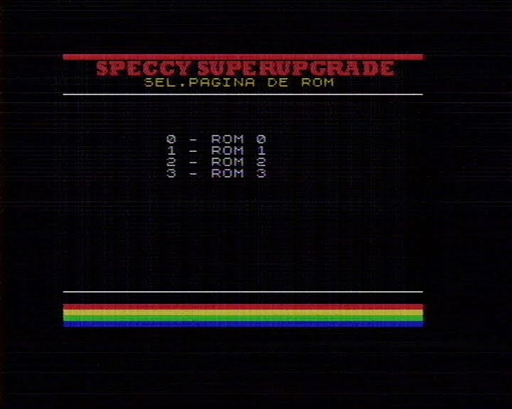
The Superupgrade Bios’ main screen shows us a list with the ROMs included in the flash memory.
To use one of them, we have to select the corresponding letter and press enter.

In this menu we have tools to test our interface:
-KEYBOARD TEST: it’ll show us visually the keys we’re pressing and the three superior bits of each half row.
When it comes to the keyboard, we use bits 0 to 4, whereas bit 6 is used for the ear input. To finish the test we press BREAK.
-JOYSTICK’S TEST: it’ll allow us to make a complete joystick’s test, asking us to press sequentially each one of the joystick’s buttons. When we get to the Sinclair’s test we should press simultaneously both of the joysticks.
In case we press “BREAK” we’ll go on with the next button though we didn’t press the right button.

-RAM TEST: you’ll make the RAM paging test, pointing out how many memory pages are available.
It’s not about a full integrity RAM test, since it just checks the paging.

-AUDIO TEST: It’ll make a musical scale sound for each one of the three AY‘s channels.

-ROM’S PAGE SELECTION: this option is thought to be for those users that don’t insert the add-on.
Remember that the memory is divided in 64kb blocks which are selectable with jumpers, as well as each block of 64kb contents four 64kb pages.
If, after select the option, we change jumpers to the desired ROM, this option will allow us to select the 16kb page that we want to execute.
As soon as we select the desired page, the system will ask us to press a key and then spectrum will be restarted, executing the program contained in the selected page.
As an example to clarify it a little bit, we’ll include a table about jumper/rom’s position to be selected from the example set which has been sent prerecorded in the kit.
We’ll be able to change just around eight 64KB blocks (slots from now on), therefore, depending on jumper’s position, when we reset with the jumpers in a concrete posicion, the system will boot up with the ROM 0 of the selected slot.
To start up the other three slot’s ROMs, the ROMs’ selection option from the tools menu will be needed.
The jumpers aren’t in order so it may be a bit confusing its use. I’m adding a table down below in order to make it clearer:

As we can see there are some ROMs which take several 16kb blocks, so in this case it’ll only have sense to start up the first block of them. For instance, if we select the second ROM of the +3 the system will be probably hangs.
We see ,in the three first columns of the table, The position jumpers must have to select a concrete slot.
For instance, the +2 grey ROMs are in the Slot 2, so we’ll have to put jumpers in up, down, up positions, starting to count from the superior jumper of the three ones of the ROM’s selection.
For this ROM especially the selector won’t be needed, since it takes the 0 position of this slot. Putting the jumpers and pressing reset will be enough.
When it comes to a ROM which doesn’t take the 0 position of a Slot, we do need the selector. That’s the case of the Spectrum’s ROM, which is in the position 1 of the slot 0, so, with the jumpers in the down down up position, we’ll select the selection ROMs’ option and we’ll press the 1. As, in this case, we don’t need to MOVE jumpers, The 48Kb's ROM will appear pressing a button.
ADDING OUR OWN ROMS
The ROMs which are recorded in the chip are just an example.
We can replace them to the ones we want, but we should take into account the following instructions.
The ROMs should have precisely 16kb, 32kb, or 64kb. If we have a ROM of a game which takes up less SPACE, we have to complete it until 16kb with an hexadecimal editor.
The ROM BIOS must always take the first position.
From that BIOS we have a menu which will allow us start up the ROMs BY SOFT just if we have the add-on installed.
In the case we use the add-on, in the 0 ROM, we have certain parameters which we’ll have to modify for each one of the ROMs and they will show us how that programme will behave.

These datum take a byte for ROM and they’re locared in $020E..$022D corresponding with the ROMs 0 to 31 ( BIOS is counted too).
In the previous table we can see that the bits 0 to 4 of each one of the bytes show us the ROM’s order number (0…31), whereas the bits 5, 6 and 7 will allow us to define the ROM’s behavior.
The bits 5 and 6 allow us to deactivate the paging of the ROM totally or partly and they’re related to the ROM’s shape.
For instance, in the case of a speccy 48Kb ROM which takes a unique 16kb block we would have to deactivate the paging completely. As we aren’t interested anymore in executing anything outside of that block of 16kb, so both bits have to be 1.
In the case of a ROM of 32kb we have to keep active the paging related to the $7FFD port which manages the change between block 0 and 1, but we’ll have to deactivate the change to the ROMs 2 and 3 which are managed with $1FFD port. Therefore, we’ll put bit 5 to 0 and bit 6 to 1.
Finally, in case of +3 ROMs, we’d better keep active full paging, so we’ll put both bits to 0.
Bit 7 will allow us to deactivate the divIDE for the cases when we want to start up a ROM , which is incompatible with divIDE, without needing to disconnect it.
Let’s use as an example the mentioned byte’s content for the example ROMSET’s ROMs:

The texts that will appear in the menu are located in $000F..$020E and they are made of a byte $0F and the text of the 15 characters long for each one of the options.
It’s important to be careful not to crush neither byte $0F nor the following option’s text.
The following table show us the beginning position of each one of the menu’s texts.
It’s important to be careful not to crush neither byte $0F nor the following option’s text.
The following table show us the beginning position of each one of the menu’s texts.

Once we have every file to include we have to gather them in the desired order, joining all of them with the command “COPY/B” or with a hexadecimal editor, checking that the final file has precisely 512kb (524.288 bytes)
I give you as an example the bat file I used to generate the file .bin to record:
I give you as an example the bat file I used to generate the file .bin to record:
del rom*.bin
copy /b BIOS.ROM+48.rom+inves.rom+tk90x.rom rom.bin
copy /b rom.bin+"plus3-spanish.rom" rom.bin
copy /b "rom.bin"+"plus2-spanish.rom"+"128-spanish.rom" "ROM.bin"
copy /b rom.bin+ "sm8es3eE.rom" rom.bin
Copy /b rom.bin+Ace_ROM.bin+tk95.ROM+gw03.rom+OPENSE.ROM rom.bin
Copy /b rom.bin+ZXTESTROM.BIN+backgammon.rom+testrom128.bin rom.bin
copy /b rom.bin+spaceraiders.rom+chess.rom+planetoids.rom+Popeye.rom rom.bin
copy /b rom.bin+qbert.rom+roj.rom+LocoMotion.rom+Gyruss.rom rom.bin
dir rom.bin
If you don’t want to make it complicated, an easy way is using as a base the file that I’ve included as an example and modifying it with a hexadecimal editor.
If we use an hexadecimal editor, we have to take into consideration that the ROMs have to be in the following positions:
If we use an hexadecimal editor, we have to take into consideration that the ROMs have to be in the following positions:

INTERFACE’S PORTS’ MANAGEMENT
For selection of ROM and RAM’s paging in 128Kb Specrtums are used $7FFD (32765) and $1FFD (8189) ports.
The change of the ROM or RAM’s page is done passing the right value to the corresponding port with an OUT, taking into consideration that each bit of that value has the following meaning:
The change of the ROM or RAM’s page is done passing the right value to the corresponding port with an OUT, taking into consideration that each bit of that value has the following meaning:
$7FFD port

-Bits 0..2 form a number of 3bits which allow us to select a page among the 8 possible of the RAM of the 128kb.
-Bit 3 is related with the shadow RAM and it permits to select the screen which will be visualized. Having bit 3 to 0 will ask the ULA to show the conventional screen, whereas if it’s to 1 it’ll mean that Shadow RAM will be shown. This feature isn’t supported in the interface.
-Bit 4 will allow us to select among the two possible ROMs in Spectrum 128k and the +2 GREY.
Remaining to 1 ROM of the 48kb is selected and to 0, 128kb’s.
In the case of the +2A/+3 another bit that we‘ll see later will be taken into account, making with the two of them a number of 2bits that will permit us to select one of the 4 ROMs available.
-Bit 5 will allow us to disable the pages.
-Bits 6 and 7 are not used.
$1FFD port:

-D0 bit will permit us to select the memory model of the +3 or the CPM
-If we have selected the CPM mode D1 and D2 bits will permit us to modify the distribuition of the RAM according to the following FACTS (This feature is not supported in interface):
-If we have selected the CPM mode D1 and D2 bits will permit us to modify the distribuition of the RAM according to the following FACTS (This feature is not supported in interface):

-If bit 0 is equal to 0, D2 bit will be the high part of the selection of the ROM, with the D4 of the $7FFD port.
We can see this bit (D2 $1FFD) as a selection of A or B chip inside the +3 and the D4 of the $7FFD as the selector of the chip’s low or high part.
-D3 is used to activate or deactivate the disk’s motor.
-D4 is the parallel port’s strobe’s signal.
-D5 and D7 are not used.
We can see this bit (D2 $1FFD) as a selection of A or B chip inside the +3 and the D4 of the $7FFD as the selector of the chip’s low or high part.
-D3 is used to activate or deactivate the disk’s motor.
-D4 is the parallel port’s strobe’s signal.
-D5 and D7 are not used.
Pagging in Pentagon
In Pentagon two more bits are added for the RAM’s page’s selection corresponding to D6 and D7 of $7FFD, leaving that port in the following way.

In our interface this page’s mode is supported having 5 bits (32 pages) for the page’s selection.
Pages’ distribution in the address space.
The address space taken by the selected page is generally $C000-$FFFF, but there are some pages that have a special treatment.
The exact distribution is sum up down below:
The exact distribution is sum up down below:

-Bank number 2 will be always visible in the rank $8000-$C000, but it will be also accessible in $C000-$F000 if we have page 2 selected.
-Bank number 5 corresponds with the $4000-$8000 screen’s memory in a +2/+3. In our interface it is not supported and it is one more bank. This could be implemented in the future according to the mcleod_ideafix instructions.
-Bank number 7 corresponds with ShadowRAM and its content will be visualized if D3 is to 1 in $7FFD port. In our interface is not implemented and bank 7 is not different to another one. Moreover, it’s impossible to implement without cutting some traces and without modify internally the Spectrum. Fortunately, there aren’t so much programs that get advantage of this feature, which in the other hand is really interesting.
Distribution of ROMs in the +3
In the +2/+3 4 ROMs come distributed in two chips (A and B), accumulating two ROMs each one of them.

In our interface, we accumulate the four ROMs in one and only slot, distributing its space in the following way:

It’s important to take into consideration that de table’s addressing is from the chip’s point of view, but the selected ROM will always access with the $0000-$3FFF standard directions’ rank.
Finally, a list about each ROM’s function:

Add-on $43B’s new port’s functionality
To be able to realize its function, add-on uses a new port which has been demanded to the ZXI specification group.
The port given to realize those tasks is $043B port.
This port is an only-wrtiting port and it has as a main functionality being able to select active the ROM inside the 512kb chip, as well as being able to deactivate divIDE and the standard pages with $1FFD and $7FFD ports.
Functionality is sum up in the following table:

Bits 0…1 would correspond with the ROM’s page and bits 2…4 with the slot’s number.
The ROM page’s change with this port will work even though pages were deactivated with $1FFD and $7FFD ports.
Bit 5 will allow us to deactivate pages with $7FFD port.
Bit 6 will permit us to deactivate pages with $1FFD port.
Bit 7 will allow us to deactivate divIDE. Actually what this port makes is screening /MREG and A15 signals avoiding THEM GOING TOWARDS THE EXPANSION BUS (PUTTING +5V), so its effect is that divIDE never detects that we are executing ROM’s directions. Therefore, it will never be activated though we have it connected.
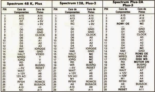
SPECCY’S SUPERGRADE’S BUS
Supergrade’s bus doesn’t coincide one by one on the front and back. The reason why it is like that is because there are some signals that are transformed to give them to the rest of the peripherals in a more convenient way for interface’s functioning.
I give you some descriptive tables of spectrum and supergrade’s bus down below, where we can see these differences.
Spectrum’s bus images have been borrowed from "El trastero del spectrum". :)
I give you some descriptive tables of spectrum and supergrade’s bus down below, where we can see these differences.
Spectrum’s bus images have been borrowed from "El trastero del spectrum". :)

FLASH MEMORY RECORDING FROM SPECTRUM
We’re now in the middle of the developing of a flash memory’s recording’s tool from Spectrum.
The next program has been developed by antoniovillena and it consists of a command's line software that, since a ROM’s file from up to 64kb, will generate a tap file ready to be executed in our Spectrum.
The next program has been developed by antoniovillena and it consists of a command's line software that, since a ROM’s file from up to 64kb, will generate a tap file ready to be executed in our Spectrum.
That tap file can be made into wav and charged by audio, or it can also be charged directly from divIDE.
If we decide to go for the charge by audio, a great idea would be update spectrum’s ROM (that it’s installed in 0 block, rom 1, in the example) with the cargandoleches ROM as a first step, and from that moment use it always to charge roms’ taps that we’re going to BURN in our flash.
In the folder we should have “SuperUpgrade.exe” file and “SuperUpgrade.bin” file.
Program’s syntax is in the following way:
SuperUpgrade <outputfile> <roms> <inputfile1> <inputfile2> .. <inputfilen>
<outputfile> Output TAP file
<roms> 4 digit number, X to preserve. 0123 full 64K, XXX3 only ROM3
<inputfileX> Input binary file/s
That is, to generate a tap with +3 ROMS we would do the following:
SuperUpgrade hola.tap 0123 plus3en41.rom
Once the tap is generated, I can pass it to my divIDE’s CF or charge it by audio, and once the spectrum is charged, a screen like the one below will appear:

In the case we have “Add-on”, we just have to press a key between 0 and 7 coinciding with the slot where we want to record ROM/s.
If, on the opposite, we don’t have Add-on , we have to change jumpers to the desired position and press a key.
Currently, our mate pachuquín is developing a frontend that firstly was thought to make easy the ROMSETs’ generation to record from a EPROMs’ recorder, but it will soon add antoniuovillena’s utility and it will permit us generate taps from a more friendly graphic interface.